How to Build a Deck on a Slope: Complete Foundation Guide 2026
Building a deck on a slope presents unique challenges and opportunities compared to flat-ground construction. Whether you’re dealing with a gentle incline or more noticeable elevation changes, a well-planned foundation is the key to long-term stability, safety, and performance. In this complete guide updated for 2026, we’ll walk through how to build a deck on a slope with a strong emphasis on the foundation system. This approach ensures your deck remains level, resists settling or shifting, and complies with common US building practices.
Many homeowners face sloped yards—especially in hilly regions like the Appalachians, Pacific Northwest, or Midwest suburbs—where natural terrain drops away from the house. A sloped site can actually enhance your outdoor space by creating multi-level views or better drainage, but it demands careful attention to the deck foundation on slope to prevent issues like uneven settling, frost heave, or lateral movement. Always start by checking your local building codes and obtaining necessary permits. For steeper slopes (typically beyond a 2:1 or 1:1 ratio, or where the drop exceeds certain thresholds), professional engineering input is often required under International Residential Code (IRC) guidelines and local amendments.
Why Focus on the Foundation When Building a Deck on a Slope?
The foundation—commonly referred to as footings, piers, or supports—is the critical first step. On uneven ground, poor footings can lead to deck failure over time due to soil erosion, water runoff, or freeze-thaw cycles. In the US, deck footings must typically extend below the local frost line (the maximum depth to which soil freezes in winter) to avoid heaving. Frost lines vary widely: for example, they can be as shallow as 12 inches in southern states or 4–5 feet in northern regions. Consult a frost line map or your local building department to confirm requirements in your area.

Additionally, sloped terrain increases lateral forces on the structure. Footings need sufficient bearing area and proper placement to resist sliding or tipping. A denser layout of footings (more supports per square foot) is especially beneficial for solid, bounce-free walking surfaces, as it distributes loads evenly and minimizes flex in the deck frame.
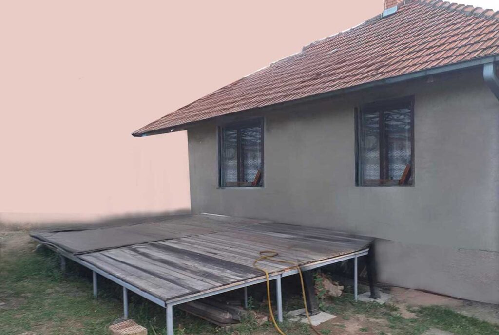
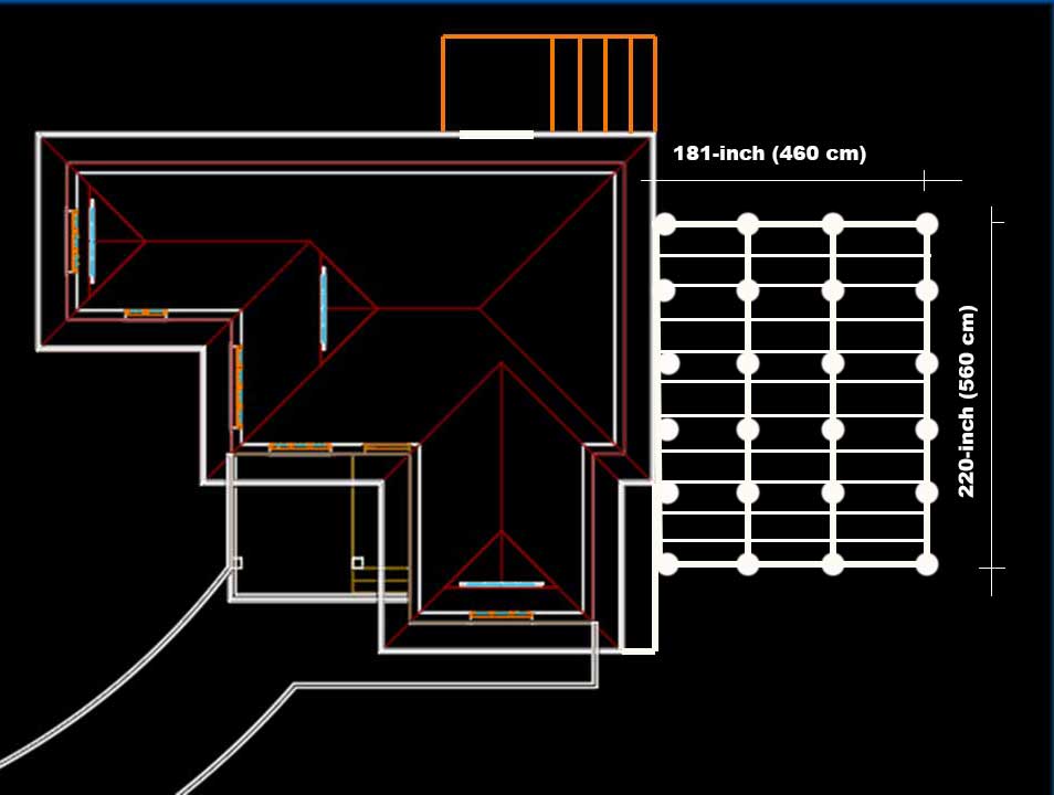
In this project, the deck measures 220 inches x 181 inches (560 cm x 460 cm)—a generous size suitable for entertaining, relaxation, or family use. Across the 181-inch (460 cm) width, there’s a natural elevation drop of about 12 inches (30 cm), creating a moderate slope. One long side sits at a height of 31.5 inches (80 cm) above grade, while the opposite side is 19.7 inches (50 cm)—a total height variation that requires variable post lengths but allows for a perfectly level deck surface once the frame is installed.
My Chosen Approach: Metal Frame and High-Density Concrete Footings
For durability and cost-efficiency, I opted for a metal construction using leftover steel pipes and sections from previous projects. Metal offers excellent longevity, resistance to rot/insects (unlike pressure-treated wood in ground contact), and strength for elevated sections. This setup creates a rigid, horizontal substructure elevated above the ground, independent of the final posts and any roof elements—allowing precise leveling before adding decking.
(Disclosure: This site participates in the Amazon Services LLC Associates Program, an affiliate advertising program designed to provide a means for sites to earn advertising fees by linking to Amazon.com and affiliated sites. If you purchase through these links, we may earn a small commission at no extra cost to you.)
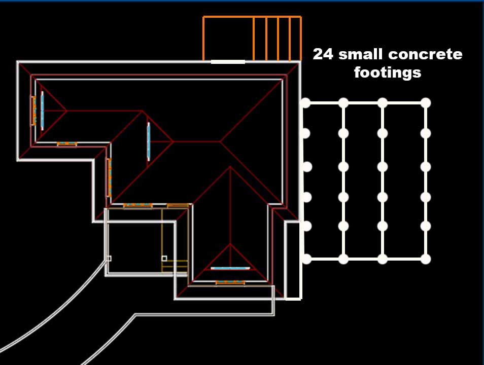
To support this frame securely on the slope, I planned 24 small concrete footings arranged in a grid of 4 rows x 6 columns. This high-density placement (more footings than a typical flat deck might need) provides superior load distribution. It eliminates noticeable flex or “bounce” when walking across the deck, even under heavy use or furniture loads. Smaller, closely spaced footings work well here because the slope isn’t extreme, and the metal frame ties everything together for added rigidity.
Important safety note: US building codes (based on the IRC and local variations) often require professional involvement for steeper slopes or significant elevation changes. If your site’s grade exceeds roughly 2:1 (a 50% drop) or involves complex soil conditions, consult a structural engineer or geotechnical expert before proceeding. Permits are almost always mandatory for attached or elevated decks, and inspections ensure compliance with frost depth, soil bearing capacity (typically 1,500–2,000 psf assumed), and setback rules.
Key Benefits of This Slope Deck Foundation Strategy
- Level platform despite uneven terrain — The horizontal metal frame bridges height differences (from 19.7 inches/50 cm to 31.5 inches/80 cm) without stepped or multi-level decking.
- Improved drainage and airflow — Elevating the structure keeps wood/metal away from constant soil moisture, reducing decay risk.
- Enhanced stability — 24 footings create a “grid” support system, ideal for sloped yards where soil can shift seasonally.
- Cost savings with repurposed materials — Using metal remnants cuts expenses while delivering professional-grade strength.
- DIY-friendly with planning — This method suits experienced DIYers, but always prioritize safety: use proper tools, wear PPE, and verify measurements multiple times.
Before breaking ground, perform thorough site assessment: stake out the perimeter, use a laser level or string lines to map elevations, and mark footing locations. Measure twice (or three times!) to account for the slope—small errors compound quickly on uneven ground.
In the sections ahead, we’ll dive deeper into preparing the site, digging and pouring footings, assembling the metal frame, installing posts/beams/joists, adding decking, and finishing touches like railings and stairs. This foundation-focused guide will help you achieve a rock-solid deck that stands the test of time.
Digging and Pouring Concrete Footings for Your Sloped Deck
Once the site is fully laid out and marked (as covered in the planning phase), the next critical step in how to build a deck on a slope is digging the footings and setting up the post supports. This is where the foundation truly takes shape—providing a stable, level base that handles the uneven terrain and variable heights (from 19.7 inches (50 cm) on one side to 31.5 inches (80 cm) on the other across the 181-inch (460 cm) width).
For this 220 inches x 181 inches (560 cm x 460 cm) deck on a moderate slope with a 12-inch (30 cm) drop, I dug 24 circular holes for small concrete footings. Each hole measured approximately 12 inches (30 cm) in diameter and about 12 inches (30 cm) deep. This depth works well for many moderate-climate US regions where frost lines are shallower (often 12 inches minimum per IRC guidelines), but always verify your local frost line first—northern states may require 36–48 inches or more to prevent frost heave. In warmer southern areas, shallower footings suffice if soil is stable and codes allow.
Precise Layout: Why Alignment Matters on a Slope
Before any digging, I measured and staked the positions multiple times using string lines, a laser level, and batter boards. The 24 footings are arranged in a grid of 4 rows by 6 columns to match the deck’s frame layout. Alignment is crucial because the metal frame will be welded directly onto embedded plates—any major misalignment could complicate welding or require extra adjustments.
That said, metal’s forgiving nature is a huge advantage here. Unlike rigid wood framing, steel allows for quick tweaks: minor offsets (a fraction of an inch) can be corrected during welding with shims, grinding, or slight bending. This flexibility makes it ideal for building a deck on uneven ground or deck foundation on slope DIY projects, where perfect precision in hole placement is tough on sloped terrain.
Pro tip for sloped yards: Use a transit level or laser to establish a level reference plane across the site. Mark each footing center so the grid stays square and parallel to the house (or desired orientation). Double-check diagonal measurements for squareness—on a slope, small errors amplify as you move downhill.
Preparing the Metal Anchor Plates
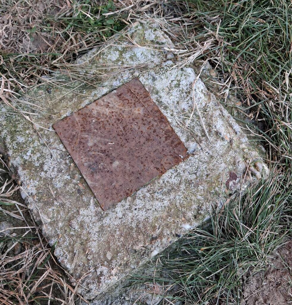
To create a strong, permanent connection between the concrete and the metal frame, prepare 24 metal anchor plates ahead of time. Each plate is 4 inches x 4 inches x 0.2 inches (10 cm x 10 cm x 0.5 cm)—a sturdy square cut from steel sheet or plate.

Weld short scraps of metal to the bottom of each plate for superior bonding:
- Use thin metal angles (L-shaped brackets), flat bars (flachovi), or short pieces of rebar/armature rod.
- Length: 4–8 inches (10–20 cm) protruding downward.
- Weld them securely in a cross or star pattern—this creates “keys” that lock the plate into the concrete, preventing pull-out or rotation under load.
These embedded anchors turn simple poured footings into reliable post bases for the metal structure. (Note: For code compliance in many US areas, consider using pre-engineered post bases like Simpson Strong-Tie if welding custom isn’t permitted—always check local requirements.)
Mixing and Pouring the Concrete
For these load-bearing deck footings on sloped yard, use a strong, reliable mix. A common DIY ratio is 3 parts gravel/aggregate to 1 part cement (with sand added for workability—often 3:1:2 aggregate:sand:cement overall for good strength around 3,000–4,000 psi). This provides excellent compressive strength for supporting deck loads.
Steps for pouring:
- Dig the holes to size, ensuring straight sides and flat bottoms. Remove loose soil and compact the base slightly for better stability.
- If needed for drainage or frost protection in your area, add a thin gravel layer at the bottom (but keep final depth compliant).
- Mix concrete in a wheelbarrow or mixer—add water gradually to achieve a firm, workable consistency (not soupy, to avoid weakening).
- Pour concrete into each hole, filling to ground level or slightly above for a mound that sheds water.
- Immediately insert the prepared metal anchor plate into the wet concrete. Press it down so the welded “keys” sink fully in (about halfway or more for embedment). Level the plate horizontally using a small spirit level—aim for all plates to align in the same plane to simplify frame welding later.
- Tap gently around the edges with a trowel or stick to release air pockets and settle the mix.
- Smooth the top surface around the plate for a clean finish.
Curing and Next Steps
Allow the concrete to cure for at least 48 hours before any welding or heavy loading—most mixes reach sufficient strength quickly for light work, but full cure takes 28 days. Keep footings moist (cover with plastic or wet burlap) in hot/dry weather to prevent cracking.
After 48 hours, you’re ready to start welding the metal frame onto these embedded plates. The dense grid of 24 footings ensures even load distribution—no noticeable bounce or flex when walking the finished deck, even on the sloped sections.
This method keeps things straightforward, cost-effective (using scrap metal), and durable for how to build a deck on a slope. In the next section, we’ll cover assembling the horizontal metal frame and posts to bridge those height differences.
Assembling the Metal Frame and Posts for a Level Deck on Slope
With the concrete footings cured and the anchor plates securely embedded (as detailed in the previous section), it’s time to build the actual structural frame. This phase transforms your deck foundation on slope into a solid, elevated platform ready for decking boards. The goal is a perfectly level surface despite the 12-inch (30 cm) elevation drop across the 181-inch (460 cm) width, using repurposed metal scraps for cost savings and durability.
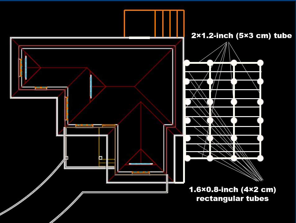
For this 220 inches x 181 inches (560 cm x 460 cm) deck, I used a combination of rectangular tubing sizes: primarily 2 inches x 1.2 inches (5 cm x 3 cm) for the main longitudinal beams (often called stringers or main supports), 1.6 inches x 0.8 inches (4 cm x 2 cm) for cross members (joists or connectors), and various short scrap pipe sections for vertical posts and bracing. These sizes provide ample load-bearing capacity for a residential deck—steel tubing in these dimensions handles typical live loads of 40–60 psf (pounds per square foot) with minimal deflection when properly supported by the dense grid of 24 footings. Aesthetics take a backseat here since the entire frame will be hidden under the final decking boards, so function and strength were the priorities.
Safety reminder: Welding metal requires proper equipment (MIG or stick welder), PPE (gloves, welding helmet, long sleeves), good ventilation, and fire safety measures. If you’re new to welding structural elements, practice on scraps first and consider having a pro inspect critical welds. Always follow local codes—some areas require certified welds for load-bearing structures.
Step 1: Installing the Vertical Posts
Start by welding the vertical support posts directly onto the embedded anchor plates. These posts bridge the slope’s height variations and create the base for your level frame.
- Begin with the 6 posts closest to the house (the ledger side). Cut and weld these to approximately 31.5 inches (80 cm) tall. These will support the higher side of the deck.
- Next, weld the 6 outermost posts (farthest from the house) to about 19.7 inches (50 cm) tall—the lower side.
- For the two intermediate rows: Weld 6 posts at roughly 27.6 inches (70 cm) and another 6 at 23.6 inches (60 cm). These fill in the gradual slope.
Due to the uneven terrain, exact heights may vary by 1–2 inches (2.5–5 cm) from post to post—measure each one individually using a laser level (ideal for precision across the slope) or a long 78.7-inch (200 cm) spirit level placed on temporary straight edges or string lines. The key is to get the top of each post aligned in the same horizontal plane. Minor discrepancies can be adjusted later with shims or slight tweaks during welding.
Step 2: Welding the Main Longitudinal Beams
Once all 24 vertical posts are in place and plumb (use a level on each), attach the main beams that run the full 220-inch (560 cm) length of the deck.
- On the 6 posts at 31.5 inches (80 cm) (house side), weld one continuous 2×1.2-inch (5×3 cm) rectangular tube along the top, spanning the entire 220 inches (560 cm). This becomes your primary beam on the high side.
- Repeat for the intermediate rows:
- Weld another 2×1.2-inch (5×3 cm) tube on the 70 cm posts.
- Then on the 60 cm posts.
- Finally, on the 50 cm posts for the low side.
You now have 4 parallel main beams running the length of the deck, each supported by 6 posts and elevated to create a level plane. Cut these tubes precisely to fit, and tack-weld first to check alignment before full welds. Use clamps or temporary bracing to hold everything steady during welding.
Step 3: Adding Cross Members for Rigidity and Support
To tie everything together and create a stable grid for the decking:
- Weld 1.6×0.8-inch (4×2 cm) rectangular tubes (or equivalent scrap pipes) as cross joists perpendicular to the main beams. Space them evenly—typically every 16–24 inches (40–60 cm) depending on your decking material’s span requirements (check manufacturer guidelines for composite or wood boards).
- These cross members connect the 4 main beams, distributing loads evenly across the 24 footings and eliminating any potential flex or bounce.
- Add diagonal bracing if needed in longer spans for extra lateral stability, especially on the sloped sections—short scrap pieces welded at 45-degree angles work great.
The result is a rigid, horizontal metal substructure that spans the slope without steps or multi-levels. The dense post/footing layout (from the earlier grid) ensures even weight distribution, so the finished deck feels solid underfoot—no noticeable deflection even with people, furniture, or gatherings.
Pro tips for welding on a slope:
- Work in sections: Complete one row of posts and beam at a time to maintain control.
- Check level frequently: Use your laser or long level across multiple beams to confirm the entire frame is planar.
- Grind welds smooth where possible for cleaner looks, though hidden framing doesn’t require perfection.
- Protect against rust: Apply a rust-inhibiting primer or paint after welding, especially in outdoor exposure.
This metal frame approach—leveraging scraps for sustainability—delivers exceptional longevity compared to wood in ground-contact areas, with no rot, warping, or insect issues. Once complete, you’re ready for the final decking layer.
In the next section, we’ll cover installing the decking boards, railings, stairs, and finishing details to complete your how to build a deck on a slope project.
Installing Decking Boards and Building Stairs for Your Sloped Deck
With the metal frame fully assembled and leveled (as outlined in the previous section), your deck on a slope now has a rock-solid substructure ready for the finishing touches. The dense grid of supports—24 footings and precisely welded posts/beams—creates a perfectly flat platform that can accommodate virtually any standard decking material. This flexibility is a major advantage: you aren’t locked into exotic or custom-sized boards, which can dramatically increase costs. Instead, stick to common, readily available options from US suppliers like Home Depot, Lowe’s, or lumber yards, keeping your project budget-friendly and straightforward.
Choosing and Installing Decking Boards
In the US, the most common deck boards are nominal 5/4 thickness (often labeled as “5/4 x 6” or similar), which means an actual thickness of about 1 inch (25 mm) after milling and planing—very close to the 2.5 cm standard you’re familiar with in Europe. This size is the industry go-to for residential decks because it provides excellent strength and minimal flex when installed over joists spaced 16 inches (40 cm) on center (the typical spacing in your metal cross members). Most pressure-treated pine, cedar, redwood, or composite boards (like Trex or TimberTech) come in this profile, with actual widths around 5.5 inches (140 mm) and lengths from 8–20 feet (2.4–6 m) for easy coverage.
- Why this works so well on a slope deck: Your metal frame’s parallel main beams and cross joists create uniform support points. No matter the board length, width, or slight variations in thickness (some composites are 0.94–1 inch / 24–25 mm), the structure handles it without sagging or bounce. This avoids the expense of specialty thick boards or custom milling—standard 5/4 boards are affordable (often $2–$5 per linear foot for treated wood, higher for composites) and widely available.
- Installation tips:
- Start from one edge (ideally the house side) and work outward. Lay the first board perpendicular to the joists, overhanging the frame edge by 0.5–1 inch (1.3–2.5 cm) for a clean look.
- Use hidden fasteners (clips/screws from below) for a clean surface or face-screw with corrosion-resistant deck screws (pre-drill to prevent splitting in treated wood).
- Maintain consistent gaps: 1/8–1/4 inch (3–6 mm) between boards for drainage and expansion—use spacers like nails or commercial tools.
- Stagger joints for strength and aesthetics—offset end seams by at least 12 inches (30 cm) in adjacent rows.
- Cut boards to fit around any protrusions (e.g., posts) with a circular saw or jigsaw.
- Secure every intersection: Fasten boards to every joist crossing for maximum stability.
This phase typically takes 1–2 days for a 220 inches x 181 inches (560 cm x 460 cm) deck, depending on helpers and material. Seal or stain treated wood immediately after installation for protection against UV and moisture—apply a second coat after 30–60 days for best results.
Building the Stairs: Custom and Practical
No deck on uneven ground is complete without safe, convenient access—especially with your slope’s 12-inch (30 cm) drop across the width and varying heights up to 31.5 inches (80 cm). Stairs provide that connection, and the beauty is there’s no one-size-fits-all rule: design them based on your needs, traffic flow, and available space. Common US practice follows IRC guidelines for safety (maximum riser height 7.75 inches / 197 mm, minimum tread depth 10 inches / 254 mm, uniform steps with no more than 3/8 inch / 9.5 mm variation), but for a moderate slope like yours, you have flexibility.
I chose two sets of stairs—one on each end—for easy access from different yard areas. This number works perfectly for my setup: sufficient without overcomplicating the build or blocking views. You could opt for one central wide staircase or even a landing midway if the total drop is larger.
- Material choice: I went with a metal construction for the stairs to match the main frame—using scrap rectangular tubing and plates for stringers (the angled supports) and treads. This ensures longevity, no rot, and easy welding to the deck frame. Later, I clad the treads with the same decking boards for a seamless look. If welding feels intimidating or you prefer simpler tools, wood stringers (cut from 2×12 pressure-treated lumber) are a classic DIY alternative—many homeowners use this method successfully.
- Basic steps for metal stairs:
- Determine total rise (vertical drop from deck to ground at each stair location) and desired number of steps. Divide rise by 7–7.75 inches (178–197 mm) per riser for comfort.
- Calculate run (horizontal projection): Multiply number of treads by 10–11 inches (254–279 mm) minimum.
- Weld or bolt stringers to the deck frame (use heavy brackets or direct weld to main beams for strength).
- Add intermediate supports if needed (e.g., concrete footings or posts at the bottom for stability on slope).
- Weld cross members for treads, then attach deck boards (cut to width, secure with screws).
- Add handrails if stairs have 4+ risers (required by code in most US areas)—34–38 inches (86–97 cm) high, with balusters spaced no more than 4 inches (102 mm) apart.
- Finish with non-slip nosing or tread tape if wet conditions are common.
For wood stairs: Cut stringers with a framing square (rise/run template), attach to deck rim joist with hangers, support bottom on concrete pads or gravel base, and clad with deck boards.
Key safety notes: Always verify local codes—some areas require permits/inspections for stairs. Ensure even risers/treads to prevent trips, and add lighting for evening use.
With decking and stairs complete, your how to build a deck on a slope project is finished: a durable, level outdoor space that handles the terrain beautifully. Enjoy the view, and consider annual maintenance like cleaning/sealing to keep it looking great for years.